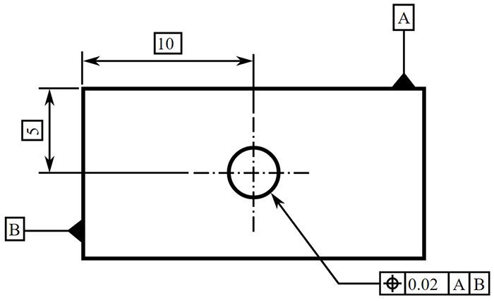
The reason that these existing GD&T standards are used to define the requirements of the DSCDM is due in part to the fact that the DSCDM is based on parts of a larger GD&T model that the author developed for STEP AP 210, Electronic assembly, interconnect and packaging design.
#Datum symbols iso#
In regard to the DSCDM, the requirements came from existing GD&T drawing-based standards (e.g., ASME Y14.5M, ISO 1101, and ISO 5459 ). “The first step in data modeling is to define the data requirements”. The model presented in STEP Part 47 will be referred to as “the Part 47 model” throughout the remainder of this paper. Additionally, a portion of the data model presented in STEP Part 47 is reviewed and a comparison is made between it and the DSCDM. This paper presents this data model, which will be referred to throughout the remainder of the paper as the DSCDM (Datum System Conceptual Data Model). The portion of the semantics that this data model defines encompasses the concepts of datum systems, datums, datum features, and datum targets. As “a data model is an effective technique to define the shareable semantics that are essential to the success of data communication in an integrated environment”, a conceptual data model has been developed that defines a portion of the semantics necessary for the electronic exchange of GD&T data among the design, manufacturing, and inspection divisions of an enterprise. However, with the advent of computer-aided design, manufacturing, and inspection equipment, the ability to exchange these requirements in a computer-sensible manner has become increasingly more desirable. Also welcome to discuss with me at Twitter or LinkedIn (OboeWu).Traditionally, geometric dimensioning and tolerancing (GD&T) requirements have been exchanged with technical drawings. To learn more about how SOLIDWORKS MBD can help you with your MBD implementations, please watch this video below and visit its product page. Datum symbol styles on the property manager.


Their results are instantly visual, so I’ll leave them for you to try out and have fun. Lastly, you can also adjust the datum symbol styles on the property manager as shown in Figure 7. Attach a datum feature symbol to a sphere diameter dimension. Figure 6 provides an example of attaching a datum feature symbol to a sphere diameter dimension.įigure 6. A symbol T not aligned with the dimension line is to define a planar datum feature, not a width feature.īesides a width, there are other applicable size features, such as spheres or holes. On the other hand, in the case of Figure 3, if the datum feature symbol B was not aligned with the dimension line, then it would have defined a planar datum feature, rather than a width feature. If there is insufficient space for the two arrows, one of them may be replaced by the datum feature triangle.” Here is an excerpt from the standard, “(The symbol shall be) placed on the dimension line or an extension of the dimension line of a feature of size when the datum is an axis or center plane. In order to specify a width feature, the datum feature symbol must be aligned with the dimension line arrow heads. It’s required by the ASME Y14.5 standard. This is not by accident or for aesthetic purpose. You can adjust the leader length of B, but cannot move B up or down on the witness line. This feature has a size dimension and the datum symbol can be attached to the witness line.Ī key point to highlight in Figure 3 is that SOLIDWORKS MBD automatically aligned the datum symbol B leader line with the width size dimension line and arrow heads. The dimension attachment option was enabled in Figure 3 because the datum feature B defined a width size feature. The symbol didn’t have a dimension to attach to. That was because the datum feature A defined a surface, not a feature of size. You may have noticed that in Figures 1 and 2, the dimension witness line attachment style was disabled. A datum feature symbol B is placed on a GD&T feature control frame. A datum feature symbol B is placed on a dimension witness line.įigure 4. A datum feature symbol A is placed on a directed leader to a surface.įigure 3.

A datum feature symbol A is placed on a surface.įigure 2. Different companies often have different preferences so SOLIDWORKS MBD supports all of them as shown in Figures 1, 2, 3 and 4. The symbol can be applied to a feature surface, a leader line, a dimension witness line or a geometric dimensioning and tolerancing (GD&T) feature control frame. There are four major types of placements. There are several frequently asked questions about the datum feature symbol placement in SOLIDWORKS Model-Based Definition (MBD), so let’s explore together in this article.


 0 kommentar(er)
